|
 Over view Over view
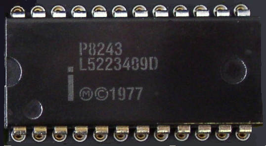
The a8243 core is the VHDL model of the Intel ™ 8243 input/ outpu t expan der.
Features
• Functionally based on the Intel 8243 device
• Five 4-bit peripheral ports: P20, P40, P50, P60, P70
• Two control signals: CS, PROG
• Four programming modes for peripheral (three write and read modes)
• 4-bit bi-directional system data bus with standard microprocessor interface controls
Interface
The pin-out of the C-8243 core has not been fixed to specific FPGA I/O, allowing flexibility with a user's application. Signal names are shown in the table.
|
Signal name
|
Signal direction
|
Polarity
|
Description
|
|
PROG
|
IN
|
-
|
CLOCK INPUT. A high-to-low transition on the PROG input signifies that the address and control bits are available on the P20 port, and a low-to-high transition signifies that data are available on the P20 port.
|
|
nCS
|
IN
|
LOW
|
CHIP SELECT INPUT. A high on the CS input inhibits any changes of the output signals or the internal status.
|
|
P20[3:0]
|
INOUT
|
-
|
4-bit bidirectional port contains the address and control bits on a high-to-low transition of the PROG input. During a low-to-high transition, the port contains data for a selected output port during the write operation, or the data from a selected port before the low-to-high transition during the read operation.
|
|
P40[3:0]
P50[3:0]
P60[3:0]
P70[3:0]
|
INOUT
|
-
|
4-bit bidirectional I/O ports. Could be programmed as the input (during the read operation), low impedance latched output (after the write operstion), or the tri-state (after the read operation). Data on pins P20-P23 could be written directly or logically mixed with previous data (AND or OR logic).
|
|
Implementation data
The core has been synthesized and implemented to different types of reprogrammable devices.
The model has been verified using the simulation environment and tested on the real hardware.
|
